In the continuing effort to improve the capability and reliability of compression equipment, it may be fruitful to look beyond the best-in-class solutions traditionally available within the compression industry. In some industries, like the manufacturing of computer chips and flat-panel TVs, processes and equipment change radically each time the size of the substrate changes. This has led to rapid developments in gas bearings and process seals. Cross pollination between industries can help more conservative industries envision possible changes, while reducing risk and development time.

One such possibility is the use of externally pressurized gas bearing technology that has seen wide acceptance in other industries as an alternative to the aerodynamic gas bearing technology typically used in compressor seals, such as in dry gas seals. The compressor and turbo industries are familiar with dynamic bearings, as most large turbine and compressor rotors have been supported on hydrodynamic oil bearings for over 100 years, and dry gas seals have been based on aerodynamic technology since their inception some 50 years ago.

Externally pressurized gas bearings employ a source of pressurized gas, whereas dynamic bearings use the relative motion between the surfaces to generate gap pressure. The externally pressurized technology has two fundamental advantages. First, the pressurized gas may be injected directly between the seal faces in a controlled fashion, rather than encouraging the gas into the seal gap with shallow groves as pumping features from the high-pressure edge. Secondly, there is no flow across the seal face; flow is from the face and out both edges.

These fundamental differences have the potential to dramatically improve the reliability of dry gas seals and increase their functionality. For instance, even seal faces that are rung together will pop open for zero-friction starts and stops when pressure is injected directly between them; this makes reliability deterministic. If the seal is running hot with the external pressure, it is possible to increase the pressure to the face. The gap then increases proportionally with the pressure, but the heat from sheer falls on a cube of the gap. This gives a new capability to adjust seals while in operation. Because there is not a flow across the externally pressurized seal face, from the pressure process side they are easier to keep dry and clean, even in multiphase compression. And because external pressurization enables controlling pressures and flows between the seal faces, gases may be segregated in a single primary seal face. This eliminates having to send process gas leakage across dry gas seals to flare or recompression, as is common practice today.

But before detailing how this is done, let’s look to why externally pressurized bearings are different from conventional dynamic technology. Externally pressurized gas bearings are also called aerostatic bearings, as they provide lift even at zero rpm. Although they do not have fine pumping groves like dynamic bearings, they do require some type of restriction for metering the gas into the gap. Air pressure is introduced directly between the bearing surfaces though precision holes, orifices, grooves, steps or porous compensation techniques. It is this process of restriction referred to as compensation that is key, but is not yet well appreciated in rotating equipment industries.

Compensation enables bearing faces to run very close together without touching, because the closer they get together, the higher the gas pressure between them gets, repelling the faces apart. As an example, under a flat-orifice, compensated gas bearing as in (Figure 1), the average pressure in the gap will equal the total load on the bearing divided by the face area. That is the unit loading. If the source gas pressure is 60 psi (214 kPa) and the face has 10 sq. in (64.5 cm2) of area and there is 300 lb. (136 kg) of load, there will be an average of 30 psi (207 kPa) in the bearing gap of 0.0003 in. (7.62 μm) with 7 scfh (0.184 Nm3) of flow.
Because there is an orifice restrictor just before the gap, if the load increases to 400 lb. (181 kg), the bearing gap is reduced to 0.0002 in. (5.08 μm) restricting flow in the gap down to 4 scfh (0.105 Nm3), so the orifice restrictor has enough flow to allow the average pressure in the gap to increase to 40 psi (276 kPa). Using these gas bearing compensation techniques, seals can be optimized for low heat generation, low flow and pressure to be sealed.
Orifice compensation is the most widely used form of compensation. (Figure 2) A typical orifice may have a hole diameter of 0.010 in. (254 μm), but as it is feeding a few square inches of area, it is feeding several orders of magnitude more area than itself, so the velocity of the gas can be very high. Often the orifices are precisely cut in rubies or sapphires to avoid erosion of the hole and changes in the performance of the bearing. Another issue is that at gaps below 0.0002 in. (5.08 μm), the area around the orifice starts to choke flow to the rest of the face, at which point collapse of the gas film occurs.
 A flat-orifice, compensated gas bearing.

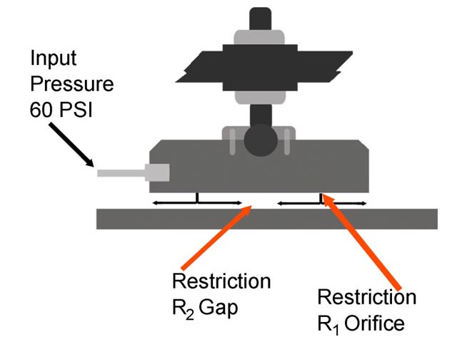
Figure 1 - A flat-orifice, compensated gas bearing.

 A flat-orifice, compensated gas bearing compared to a porous air bearing

Figure 2 - When air pressure bleeds evenly from the entire surface area of the face, the whole surface area develops pressure even when grounded, like a hydraulic cylinder. Orifice bearings have only the area of the orifices and any grooves for the pressure to establish initial lift. The even pressure profile of porous gas bearings makes them more suited for the application to sealing technology.

There is a more elegant method for providing compensation. The ideal air bearing design would supply pressure equally across the whole face of the bearing and automatically restrict and dampen the flow of air to the face at the same time. This can be achieved by diffusing air through a porous bearing or seal face. It happens that graphite, carbons and ceramic silicon carbide — all common to the rotating equipment industries — are naturally porous and can be used for both the compensation and the bearing or seal face.

The stability of porous media compensation is due to the damping effect from the torturous passageways the gas must flow through to reach the face. This damping effect makes it difficult for the volume of air in the gap to change quickly, resulting in a naturally stable gas film that cannot be plugged by particulates. Even with the supply tubes and/or ports completely full of particulates (sand, dust, etc.), it still does not create as much restriction as the porous media itself. Plugging is a serious issue for orifice compensation. In the case there is contact, graphite and carbons are an excellent plain bearing material.

Porous bearings offer two key benefits. The first is that externally pressurized porous gas bearing technology has been optimized to achieve high pressures in bearing gaps and low flows, which is just what is needed for noncontact seals, as the high pressure in the gap is an impassable barrier for anything at a lower pressure. Second, by injecting seal gas directly into the seal gap, both the pressures and flows in the gap may be controlled, enabling gas segregation in the primary seal face and eliminating the practice of sending process seal gas to flare.

Conventional dry gas seals (Figure 3) have a flow across their face, from the high-pressure to the low-pressure side. Moisture or oils from the process are naturally carried into the seal gap by the flow from this pressure differential, where they carbonize or boil from the shear and cause reliability issues. Trying to stop this with clean dry seal gas is like trying to stop water from flowing downhill, it is fighting nature. Hundreds of cubic feet of process seal gas at a fraction of a bar above the process are used to – hopefully – protect the seal. Most of it is a waste as only about 1% of this will actually leak across the seal faces. Although this leakage is small, it often requires flaring or collection and recompression.
With externally pressurized porous gas bearing technology, (Figure 4) gas passes through a porous seal face to create a pressure in the seal gap that is higher than the process pressure. The flow to vent is the same, but about the same amount that is vented flows back into the process. The advantage is that moisture will not enter the gap because the gap is at a higher pressure. It would be like water running uphill. So, there is no flow across the seal face from the process, increasing reliability. The process seal gas required for the externally pressurized bearing is 1/100 of the seal gas used with conventional dry gas seals, but at 4 bar above the process. The higher pressure differential and 1/100 of the flow requirement makes it easier to condition the seal gas reliably.
A zero-emissions seal (Figure 5) has all the advantages of an externally pressurized porous seal, but additional gases may be segregated in a single seal face. This is where all the process gas stays in the compressor and all the barrier gas exits the compressor. By using two externally pressurized bearing gases, (process seal gas is used on the process side of the seal face and a barrier gas on the vent side) their relative pressure may be adjusted to steer the highest pressure point in the gap to be between the gases. At this point, all process gas flows back to process and all the barrier gas exits the compressor, eliminating fugitive emissions.
Conventional Dry Gas Seal

Figure 3 - Conventional Dry Gas Seal

A New Way seal with externally pressurized porous gas bearings

Figure 4 - A New Way seal with externally pressurized porous gas bearings.

Zero-emissions seal

Figure 5 - Zero-emissions seal

Test rig for testing segregation of gasses

This test rig is used to test the segregation of gasses in a single seal face at speed. It is equipped with a particle counter sensitive to 50 parts per million.

This article by Drew Devitt originally appeared in the November, 2017 issue of CompressorTech2. A PDF can be downloaded by clicking here.