Hopefully, the take away ideas from this article will be new ways of solving your old problems. The basic idea is to use externally pressurized gas bearing compensation techniques to: (1) increase the pressures that can be sealed against, (2) reduce the flow of buffer gas, barrier gas, or shop compressed air, and (3) eliminate friction, heat, and wear in seals and bearings for bulk powder processing.
First let’s cover a bit of gas bearing technology. There are two main types of gas bearings: aerodynamic gas bearings and externally pressurized gas bearings. Dry Gas Seals (DGS) often used in high speed compressors are an example of aerodynamic technology. It would be great if DGS worked in powder applications, since dry and frictionless seals are just what the powder industry needs.
Aerodynamics seals like DGS generate lift only when you have the relative surface speed that allow the hydrodynamic features to operate properly. Unfortunately, in most powder applications, the motion is relatively slow compared to gas compressors where the seals are most frequently employed.
Aerodynamic bearings depend on relative motion between the bearing surfaces and usually some type of spiral or “T” grooves to pump air pressure between the bearing lands. This bearing action is very similar to hydroplaning in your automobile when hitting a puddle of water at high speed, which is why we have tread in our tires. At a lower speed, your tire would cut through the water to the road. In just this way, aerodynamic bearings require relative motion between the surfaces N when there is no motion or when the motion is not fast enough to generate the air film, the bearing surfaces will come into contact. Aerodynamic bearings are often referred to as self-acting bearings. Other examples of this type of bearing would include read-write heads flying over a spinning memory disk, or in oil, crankshaft, and camshaft journals. Another issue with aerodynamic seals is that the flow is from one side of the seal to the other, across the seal face. So this doesn’t work well when there’s powder on the higher pressure side.

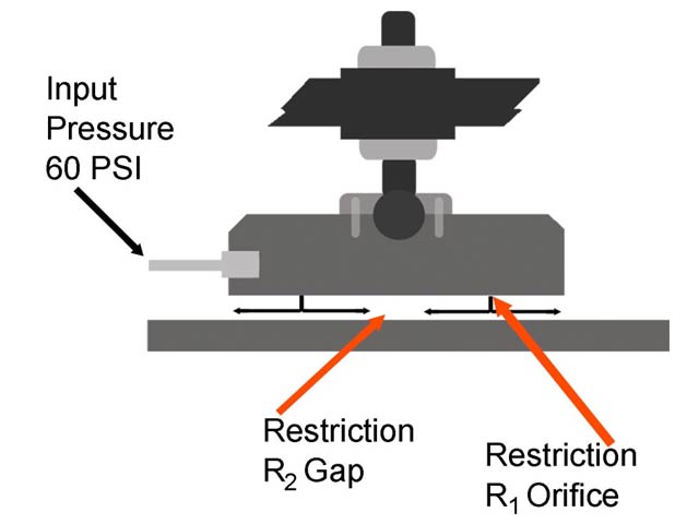
Figure 1: This is a cutaway side view of a typical orifice air bearing found in a coordinate measuring machine (CMM). If a pneumatic system is to be considered an "air or gas bearing," it needs to have a restriction upstream of the bearing gap restriction.

Figure 2A: This is an end view of a shaft through a throttle bushing with an annular groove, centered axially in the ID of the bushing. There is no force to center the shaft in the bushing, as the barrier gas just follows the groove to side with the largest gap.

Figure 2B: In the same case as 2A, except there are restrictive orifices inserted in the ID holes, and there is no annular groove. There is now a centering and stabilizing force. As the shaft moves toward an orifice, the restriction in the bearing gap increases relative to the orifice restriction, and so the orifice lets in more of the supply pressure, pushing the shaft back to center. There is an equal and opposite complimentary change in pressures on the opposite side. This is compensation.

Figure 2C: Still, this restoring force should be equal around the 360° of the base. Many expensive orifices may be required to achieve this with orifice technology.

Figure 3: When air pressure bleeds evenly from the entire surface area of the face, the whole surface area develops pressure even when grounded. Orifice bearings have only the area of the orifices and any grooves for the pressure to establish initial lift. The even pressure profile of porous gas bearings makes them more suited for application to sealing technology.

Figure 2D: By positioning the annular groove under the porous media, it feeds millions of submicron sized orifices that are formed naturally and very evenly distributed across the face.
This porous gas bearing technology is applied in both bushing and face type seals. The face type seals are easier to achieve very small gaps with, as the air gaps are set by relative loads, preloads, or pressures; whereas the fixed geometry and hoop stiffness of journal bearings means bearing clearances need to be match machined closely and ambient temperature should be somewhat consistent. Still, the convenience and tight radial package make the bushing approach appropriate for many bulk powder applications.
In summary, the use of porous media technology in bulk powder processing should provide the industry with three key advantages: sealing against higher pressures, reduced flow of buffer or barrier gases, and the elimination of friction, heat and wear for seals. These seals are envisioned as being used for powder, bulk solids and wet mixture handling equipment such as screw conveyors, paddle/ribbon mixers, rotary valves and other similar equipment vented to the atmosphere. They are also appropriate for seals and bearings in fans and blowers. High-speed applications are also a strong suit for gas bearings, especially in dusty environments. Visit Flowserve at booth #2726 at this year’s Powder & Bulk Solids Exhibition to observe this technology up close.

Figure 4: Submersed underwater with 60 psi input pressure, 3 SCFH bleeds evenly out of the face of a 2.5Vinch diameter New Way porous bearing. This bearing carries 150 lbs. of load at 0.0002Vinch air gap.

Figure 5: Porous gas bearing seal designed as a double opposed isolation seal in a very compact package. It can completely contain 30 psi with 0.5 SCFM of barrier gas @45 psi.

